|
|
|
|
|
| |
TECHNICAL INFORMATION |
|
|
Drilling, Coring & Logging
|
General drilling programme
-
3 vertical wells, each about 800 m TVD, 5 ½" OD production casing
-
2 observation (OW1, OW2), 1 injection well (IW)
-
target: Stuttgart-Formation, saline sandstone aquifer
-
oriented perforation in reservoir
-
3 1/2" injection string incl. packer in IW
|
|
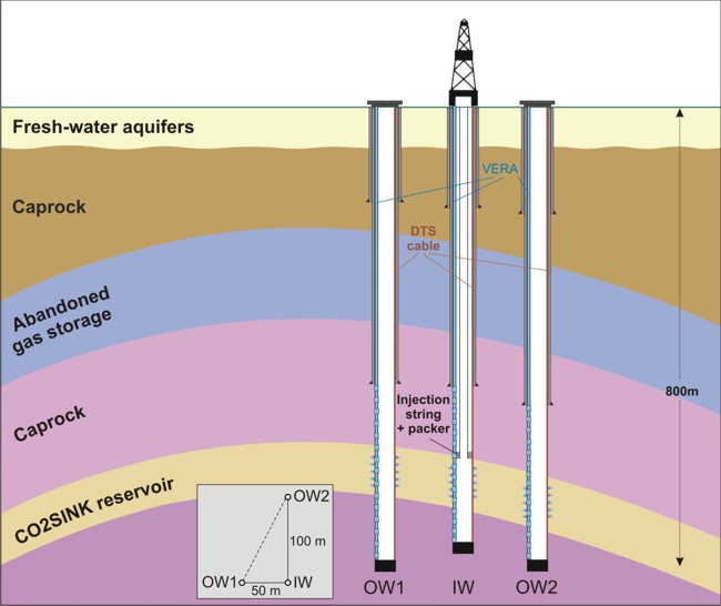
Fig. 1: CO2SINK reservoir development scheme
|
|
Well profile
| |
Depth up to ... |
Diameter |
|
Quality |
Connection |
[m] |
[inch] |
[mm] |
[lb/ft] |
|
|
Standpipe |
30 |
24 |
610 |
125.50 |
min. X-52 |
according to API |
Anchor string |
150 |
18 5/8 |
473 |
87.50 |
min. H-40 |
BTC |
Reserve string |
ca. 340 |
13 3/8 |
340 |
54.50 |
min. K-55 |
BTC |
Technical string |
590 |
9 5/8 |
244 |
36.00 |
min. K-55 |
BTC |
Production string |
800 |
5 1/2 |
140 |
20.00 |
stainless steel 13Cr80
(outer coating)
|
Premium
(gastight)
|
Injection string |
680 |
3 1/2 |
89 |
9.30 |
min. C-95 |
Premium
(gastight)
|
Casing programme; the lower part of the production casing (from ~469 to 802m - 333m) will be made up of 13Cr80 for improved corrosion resistance (see material selection), for the top hole section above the cap rock L-80 carbon stell will be used
|
|
Downhole pressure gauge above permanent production packer in ~700 m depth; optical fibre service line fed back to surface on injection string (attached via metal cable); the cable specifications are:
- Optical cable encased in 1/4" OD x 0.028" wall Incoloy 825 tube
- Encapsulated to 11mm x 11 mm square in polypropylene for full 150 Deg C compatibility
|
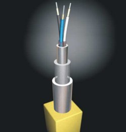
Source: Weatherford
|
|
|
Behind casing sensor (BCS) programme
IW, OW1 & OW2:
- 2x 5.5 mm OD optical fibre cable strings (HDPE coating)
- 1x 0.56 in. (14.22 mm) OD electric cable (PU coating)
- cable protectors with one cable feed-through of 1"
|
Attachment of BCS on casing strings with metal control line protectors (e.g. MCLP by Weatherford, design to be specified). The protectors simultaneously act as casing centralizers and are mounted on the pipe body. Thus there design only depends on the OD of the casing and the borehole size.
The well head equipment has to be customized for the BCS programm. A technical concept is currently being established. In case of a conventional well head system a casing spool with a 45° outlet below the slips section is required. |
|
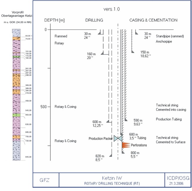
Fig. 2: Casing Scheme Injection Well IW
|
|
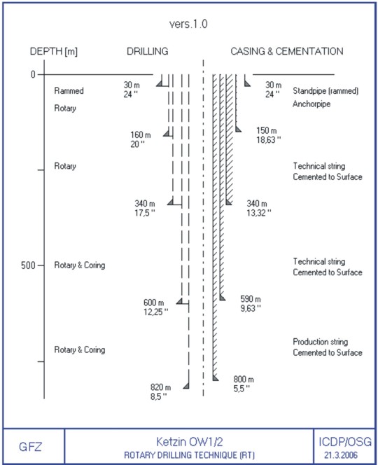
Fig. 3: Casing Scheme Observation Wells OW1 and OW2
|
Coring Programme
Formation |
OW1 |
IW |
OW2 |
Weser-Formation |
x |
x |
- |
Stuttgart-Formation |
x |
x |
- (optional) |
Grabfeld-Formation |
x |
(x) |
- |
|
|
Coring Program Observation Well OW1:
Formation |
Coring Section |
Run Length |
Coring Runs |
Weser Fm. |
563 - 590 m |
9 |
3 |
Weser Fm. |
626 - 635 m |
9 |
1 |
Stuttgart Fm. |
635 - 725 m |
9 |
10 |
Grabfeld Fm. |
725 - 734 m |
9 |
1 |
Total core section: 135 m
|
|
Coring Program Injection Well IW:
Formation |
Coring Section |
Run Length |
Coring Runs |
Weser Fm. |
626 - 635 m |
9 |
1 |
Stuttgart Fm. |
635 - 725 m |
9 |
10 |
Grabfeld Fm. |
- |
- |
- |
Total core section: 99 m |
|
Coring Program Observation Well OW2:
Formation |
Coring Section |
Run Length |
Coring Runs |
Weser Fm. |
- |
- |
- |
Stuttgart Fm. |
635 - 725 m |
9 |
optional |
Grabfeld Fm. |
- |
- |
- |
Total core section: optional
|
|
|
Logging Programme
|
|
Logging Section |
Bit Size |
Casing |
Lithology |
Log Type |
Estimated Log Time |
|
0-150 m (open hole) |
20" |
18 5/8" |
Basis Rupelfolge |
Caliper, Borehole Orientation, Spectrum GR, Density, Sonic |
5 hr |
|
0-150 m (cased hole) |
20" |
18 5/8" |
Basis Rupelfolge |
Cement Bond Log, Variable Density Log |
5 hr |
|
OPTIONAL:
150-360 m (open hole)
|
17 1/2" |
13 3/8" |
Weser Formation |
Caliper, Spectral GR, Mud Parameter, Borehole Orientation, SP, Sonic Velocity, Resistivity, Bulk density |
12 hr |
|
OPTIONAL:
150-590 m (cased hole)
|
17 1/2" |
13 3/8" |
Weser Formation |
Cement Bond Log, Variable Density Log |
5 hr |
|
150-590 m (open hole) |
12 1/4" |
9 5/8" |
Weser Formation |
Caliper, Spectrum GR, Mud Parameter, Borehole Orientation, SP Sonic Velocity, Resistivity, Bulk Density, Neutron Porosity |
12 hr |
|
150-590 m (cased hole) |
12 1/4" |
9 5/8" |
Weser Formation |
Cement Bond Log, Variable Density Log |
5 hr |
|
590-802 m (open hole) |
8 1/2" |
5 1/2" |
Grabfeld Formation |
Caliper, Spectral GR, Mud Parameter, Borehole Orientation, SP Sonic Velocity, Resistivity, Bulk Density, Neutron Porosity |
24 hr |
|
590-802 m (cased hole) |
8 1/2" |
5 1/2" |
Grabfeld Formation |
Cement Bond Log, Variable Density Log, Ultrasonic Imager Tool |
12 hr |
|
590-802 m |
8 1/2" |
5 1/2" |
Grabfeld Formation |
Optional: Pulsed Neutron, RST, NMR, FMI, DSI, USIT |
36 hr |
|
(700 m) |
|
|
|
Downhole Fluid Sampler |
5 hr |
Preliminary downhole logging programme for all three wells IW and OW1+2
|
|
|
|
| |
|