|
Safety & Risk Assessment
(CO2SINK Work Package 4.1)
The primary challenge for geological storage of CO2 is to ensure that the stored CO2 is retained over a sufficiently long period of time. All of the individual and specialist technical activities within the CO2SINK project are designed to contribute to our understanding of this challenge. Furthermore, this project must be conducted within time and budget constraints, and under operating conditions that are safe for on-site workers. The project management recognises that the key to success is to organise an integrated, cross-discipline methodology for risk assessment and management. In practice, this means the combining the individual risk issues identified at the specialist level into a common, comprehensive decision model and framework that will help project leaders to reduce risks to levels that are as low as reasonably practicable (ALARP).
The top-level risks include all aspects of safety, cost, schedule and system performance, i.e., that the storage facility will retain the injected CO2 for the very long time required to mitigate climate change, as roughly illustrated on the sketch here.
The goals of the risk management work process for the CO2SINK project are therefore to identify specifically for this CO2 storage site
- All potential sources of risk, including those to the local community.
- Project decisions related to those risk sources,
- Alternative, mitigating actions to reduce risks to ALARP.
These mitigating actions will be implemented according to a plan that is specifically designed to mitigate risks identified by specialists within each technical discipline. Part of this plan will be a formal safety case for the storage site. Note that if the risks cannot be reduced to sufficiently low levels, project management may conclude that the project cannot proceed without significant modifications.
The CO2 storage site near Ketzin is a place of sound geoscientific knowledge of the ground thanks to a comprehensive research program and gas storage utilization within more than four decades. The site is considered suitable (meaning "safe containment") for a limited injection program as required for a research project. The ultimate barrier of the storage complex is the so called "Rupelian clay", which successfully acted as caprock during active seasonal storage of town gas at Ketzin in the period 1964 to 1970 and during the storage of natural gas in the same reservoir from 1970 to 1992. The ground below the Ketzin site is considered suitable for a long-term storage of CO2 within the aims and frameworks of this project.
Some of the central tools and work processes involve a geological model of the storage reservoir and the geosphere above it, including adjacent subsurface formations. The reservoir model will be constructed using several different data sources and types related to the description of the subsurface, as illustrated below. The geological/reservoir model will ultimately show where injected CO2 is stored and how it might move and dissolve in the native reservoir fluids.
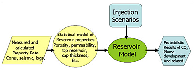
This project will also use the latest fit-for-purpose industry databases for CO2 storage projects developed in connection with other EU Frame Programme research work. This type of database is known as a features, processes and events (FEP) database and includes all risk sources for a generic CO2 storage project. This will be adapted to match the specific setting for the CO2SINK storage site. The database is part of the overall work process as illustrated in the diagram here.
These diagrams show a 3-D digital model of the underground, a part of the FEP database, a schematic well bore, and some storage migration scenarios that will be integrated into a quantitative model for analysis of overall leakage risks.
|